Plc bradley 755 powerflex drives wiring electrical Powerflex drives ac allen bradley Terminal 11 is the 24vdc supply that was terminal 9 on the powerflex 70
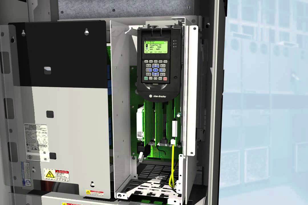
PowerFlex 750 Series Comparison – 753 vs 755 | Do Supply Tech Support
Allen bradley powerflex 755 wiring diagram Powerflex 755 wiring diagram Powerflex 755 wiring diagram
Power flex 525 manual
Powerflex 70 manual wiring diagramTwo-wire control Allen bradley powerflex 755 wiring diagramPowerflex 755 wiring diagram.
Powerflex bradleyPowerflex 755 bradley Powerflex 750 series comparison – 753 vs 755Powerflex 755 wiring diagram.

Allen bradley powerflex 400 wiring diagram
Powerflex 753 wiring diagram ethernetPowerflex 755 troubleshooting guide Powerflex 523 wiring diagramAutocad electrical allen bradley symbols.
Powerflex 755 wiring diagramPowerflex 755 wiring diagram Powerflex 755 wiring diagramHow to read and understand a powerflex 755 wiring diagram.

Powerflex 755 user manual
Move the jumpers into the current mode position for 0-20ma. wire toPowerflex 755 parameter list and uses Powerflex 525 parameter, input and output programming tutorial inPowerflex 755 series.
Two-wire control[diagram] powerflex 755 wiring diagrams Powerflex wiring bradley 4m vfd pump© rockwell automation.
Three-wire control wiring model external power powerflex 750 drive 120
Powerflex 755 ac drivesAllen bradley powerflex 755 wiring diagram Powerflex 755 wiring diagramAllen bradley plc wiring diagram.
Powerflex 755 wiring diagram .


Powerflex 755 Series

Powerflex 755 wiring diagram

PowerFlex 750 Series Comparison – 753 vs 755 | Do Supply Tech Support

Allen Bradley Powerflex 755 Wiring Diagram

Move the jumpers into the current mode position for 0-20mA. Wire to

Powerflex 755 Wiring Diagram - Wiring Diagram

Two-Wire Control

Terminal 11 is the 24VDC supply that was terminal 9 on the PowerFlex 70
